lophtware

lophtware projects

USB Type-C / PIC32 Breakout Board
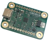
The USB Type-C / PIC32 Breakout Board is a breadboarding and prototyping aid with firmware providing common functionality for a variety of general-purpose use-cases. The board aims to be a more flexible offering compared to the FT232-type breakout boards by incorporating a 32-bit PIC. The major design goal is plug-n-play for rapid prototyping without the need for an in-depth knowledge of USB or having to install custom drivers.
The chosen USB protocol for the stock firmware is HID (Human Interface Device) because it is ubiquitous and does not require drivers or (significant) configuration of the Host to be up and running fast. It should just work.
Highlights and features
- A 32-bit PIC32MM0256GPM028 MIPS microcontroller running at 24MHz and featuring:
- 256KiB of Flash for program memory and configuration
- 32KiB of RAM
- 11 General Purpose Inputs / Outputs (GPIO) broken out to 0.1” headers for bit-banging, status flags or microcontroller peripherals
- An I2C bus controller capable of operating as both Master and Slave
- An SPI / I2S controller (Master only for the default firmware)
- A Universal Asynchronous Receiver / Transmitter (UART) controller
- A 12-bit Analogue-to-Digital Converter (ADC)
- Analogue comparators
- Pulse Width Modulation (PWM) controllers
- Capture / Compare / PWM modules
- Timers
- Four Configurable Logic Cells (CLCs)
- USB 2.0 Full Speed (12Mib/s) Compatible Human Interface Device (HID) Endpoints, negating the need for custom drivers
- USB Type-C power / CC pin capability detection - note this is NOT USB PD (FUSB303)
- Programmable both via USB Type-C Debug Accessory Mode to allow firmware updates without opening an enclosure, or via GPIO pins (ICSP)
- A +3.3V Low Drop-Out (LDO) Linear Regulator (AP2114HA) capable of supplying a minimum 1A (derated to 150mA at 50 Celsius ambient, without a heatsink)
- Over-current protection of 1.5A (typical; 1.2A-1.8A) to protect the Host from breadboard disasters (NCP367DPMUEC)
- Over-voltage protection up to +24V to protect the device and any breadboard circuitry (NCP367DPMUEC)
- All GPIO pins capable of sourcing / sinking 10mA, enough to drive LEDs (remember a series resistor !)
- Small board with mounting holes, occupying less than the 12-hole width of a standard breadboard strip
- Firmware source, board schematics and examples
See Also
Hello, World ! for the obligatory blinking LED.
The USB Device Model page for a description of the device’s USB structure and communications protocol.
The I2C page for information on interacting with the device via an I2C bus.
For applying firmware updates and uploading custom firmware there are two methods of In-Circuit Serial Programming.
And as with everything else in life, there are a few ‘quirks’…

This documentation is licensed under a Creative Commons Attribution-ShareAlike 4.0 International Licence.